


SmartPad System: Engineering Reference for Corrosion Under Pipe Supports (CUPS)
By Hani Almufti · Engineer & Senior Manager, Cogbill Construction
TR-SMARTPAD-001 · Revision 1 · Technical review: November 2026
Published November 9, 2026
| Document Control | |
|---|---|
| Technical Reference | TR-SMARTPAD-001 |
| Revision | 1 |
| Last Technical Review | November 2026 |
| Manufacturer | Cogbill Construction, LLC |
| Brand / Product | RedLineIPS / SmartPad System |
| Author | Hani Almufti, Engineer & Senior Manager |
| Classification | Engineering technical reference; manufacturer-authored with external source verification |
1. Abstract
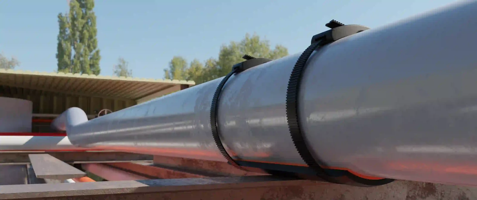
Corrosion under pipe supports (CUPS) is a localized integrity threat created by the interaction of support geometry, coating condition, moisture and contaminant retention, restricted oxygen transport, mechanical movement, and limited inspection access. The Energy Institute identifies the pipe/support interface as particularly vulnerable because deterioration can be highly localized and difficult to inspect, while HOIS/BINDT work shows that advanced nondestructive testing (NDT) may be required when direct access is unavailable. [1, 2]
The RedLineIPS SmartPad System is a removable, mechanically retained pipe-support interface manufactured by Cogbill Construction, LLC. It combines a contoured fiber-reinforced polymer (FRP) saddle, a factory-bonded closed-cell Hydroseal gasket, 19-mm (3/4-in.) PA66 SmartBand Standard retention bands and buckles, and SmartTool installation tooling. The system is intended to modify the pipe/support contact so that the pipe coating is protected, direct metallic contact is interrupted, moisture entry at the compressed pipe/pad interface is limited, thermal movement is preferentially transferred to the FRP-to-support interface, and the actual pipe surface can be exposed for inspection without destroying a permanently bonded wear pad.
This reference consolidates the SmartPad engineering basis, primary laboratory reports, component-manufacturer data, published field evidence, CUPS inspection guidance, and applicable piping-integrity standards. It deliberately distinguishes proof-test observations from design allowables, component data from finished-product properties, manufacturer field records from independent evidence, and water-sealing terminology from electrical-enclosure certification. SmartPad is a CUPS-mitigation and interface-management system; it is not a pressure-boundary repair, pipe anchor, line stop, guide, or substitute for owner engineering.
2. Scope, Intended Use, and Evidence Framework
2.1 Scope and intended applications
This reference addresses above-ground industrial piping where a pipe bears on structural steel, a shoe, a saddle, a beam, or another support surface and where CUPS, coating damage, inspection access, thermal movement, or local vibration are concerns. The standard RedLineIPS SmartPad product range used in this article is 1/2 in. through 72 in. NPS. Geometry, coverage angle, thickness, and length are selected to suit the pipe outside diameter, support width, expected movement, load path, access, and owner requirements. [23]
SmartPad may be used for new construction or retrofit work. Retrofit use requires the owner to establish that the pipe is structurally acceptable, that any existing corrosion has been properly evaluated and remediated, and that temporary lifting or unloading can be performed safely. SmartPad does not restore lost wall thickness and is not a repair under API 570, ASME PCC-2, or API 579-1/ASME FFS-1. [3, 5]
2.2 Evidence classes used in this reference
Technical claims are separated by source type because a resin data sheet, a prototype proof test, a manufacturer field record, and an industry standard answer different engineering questions. The following hierarchy is used throughout this reference:
| Evidence class | Examples | Appropriate use |
|---|---|---|
| Primary third-party test report | Houston Metallurgical Laboratory Tests 484-19 and 489-19 | What the specific tested specimen and fixture sustained under the reported test. |
| Component-manufacturer data | HCL SmartBand literature; INEOS DERAKANE data; Hydroseal technical data | Material/system properties within stated test conditions and product configurations. |
| Industry code / guidance | Energy Institute CUPS guidance; API 570/RP 574; API 579-1/ASME FFS-1; ASME B31.3; NEMA/SAE/ASTM | Definitions, inspection/assessment framework, test methods, and engineering context. |
| Published field case | Offshore Magazine Gulf of Mexico case study | Documented service chronology and field observations, with limitations of the published method. |
| RedLineIPS manufacturer specification / field record | Size range, installation practice, friction-model basis, Gulf Coast service records | Product-level requirements and manufacturer experience; not independent validation. |
2.3 Terminology that must not be conflated
Several terms used loosely in pipe-support literature have materially different meanings. This reference uses them as follows:
- Proof load: the force applied to a particular specimen during a reported test. A proof load is not automatically a working load limit, allowable support reaction, fatigue rating, or code capacity.
- Maximum system strength: HCL’s published strength of the band-and-buckle system under the specified test setup. It is not the same as installation force or long-term retained force. [8, 9]
- System force / global strap tension (F): HCL terminology for the circumferential system force. HCL illustrates ideal band-leg tension as T = F/2. [9]
- Retention force: the remaining system force after the fitting tool is released, under the manufacturer’s test conditions. [8, 9]
- RedLineIPS band-force basis: approximately 500 lbf per installed band assembly, or approximately 1,000 lbf combined for a normal two-band analytical model. This is a RedLineIPS engineering/modeling basis, not an HCL-published installation setpoint. [23]
- NEMA 4-level water exclusion: RedLineIPS terminology for the properly compressed gasket interface. It does not mean that the SmartPad is a NEMA Type 4 electrical enclosure. [15, 23]

3. Corrosion Under Pipe Supports: Mechanisms and Integrity Significance
3.1 Why the support interface is a high-risk location
CUPS is not a single corrosion mechanism. It is a location-specific integrity problem in which geometry and access can amplify several degradation mechanisms. The contact or near-contact region can retain rainwater, condensation, washdown water, salt spray, cooling-tower drift, process residues, dirt, rust scale, and biofilm. The same region is often shaded from airflow and difficult to coat, clean, inspect, or dry. The Energy Institute therefore treats CUPS as a significant piping-integrity threat and specifically links prevention, inspection strategy, remediation, support design, and line lifting. [1]
The basic electrochemical requirement is the same as elsewhere on carbon steel: an anodic reaction, a cathodic reaction, an electrolyte, and an electron path. For iron in aerated neutral water, the simplified reactions are:
Fe → Fe²⁺ + 2e⁻
Anodic metal dissolution
O₂ + 2H₂O + 4e⁻ → 4OH⁻
Cathodic oxygen reduction
Within a narrow wet crevice, oxygen transport is restricted. Differential aeration can make the oxygen-depleted region beneath the support relatively anodic to adjacent, better-aerated steel. Chlorides and other dissolved species can concentrate as wet/dry cycles repeat. Once the coating is damaged or disbonded, localized pitting and crevice attack can advance beneath a region that remains visually hidden. [1, 7]
3.2 Coating damage, fretting, and thermal movement
The support is also a mechanical contact. Thermal expansion, vibration, pipe sag, pressure transients, support settlement, and small alignment errors can create repeated relative motion. If the pipe coating itself becomes the routine sliding surface, the coating can abrade, polish, crack, or disbond. Corrosion then acts on a surface that has lost its primary barrier. Small-amplitude motion can also produce fretting debris that retains moisture and salts, increasing time of wetness at the contact region.
This interaction is why CUPS should not be reduced to “metal touching metal.” The relevant engineering system is:
Coating + environment + geometry + movement + load + drainage + inspection access.
Direct metal-to-metal contact can contribute to abrasion and, when electrochemical conditions exist, galvanic effects; however, ordinary carbon-steel-on-carbon-steel contact does not automatically create galvanic corrosion.
3.3 Moisture, chlorides, deposits, and MIC
Coastal and offshore service intensifies CUPS risk because deposited chlorides can absorb moisture and extend the period during which the support remains electrolytically active. Process plants add additional contaminants: cooling-water salts, fertilizer dust, sulfur-bearing deposits, acids or alkalis, hydrocarbon residues, and cleaning chemicals. Deposits can create local occluded cells even where the bulk environment appears benign.
Microbiologically influenced corrosion (MIC) is also possible when a support region remains persistently wet and contains nutrients or deposits. MIC is not assumed to be present simply because a support is damp; it requires microbiological and environmental conditions that support the relevant organisms. Where MIC is suspected, the owner’s corrosion-control program should establish the appropriate sampling and assessment method.
3.4 Consequence of hidden wall loss
CUPS can progress from coating failure and local pitting to measurable wall loss, leakage, rupture, loss of bending stiffness, or structural sag. A 2026 Institution of Engineers, Malaysia (IEM) Journal case study reported an offshore process-piping location with 75.6% localized wall loss and a minimum measured thickness of 2.0 mm versus a 2.8 mm structural minimum used in that study. The case is not a prevalence statistic, but it illustrates why direct condition assessment and fitness-for-service decisions matter once significant wall loss is found. [7]
Where corrosion is discovered, the support-interface product is no longer the primary engineering question. The owner must determine remaining thickness, flaw geometry, pressure containment, external loads, and continued-service acceptability under the applicable piping and fitness-for-service framework. API 570 and API RP 574 provide in-service inspection and piping-component practices, while API 579-1/ASME FFS-1 provides assessment methodologies for damage such as local metal loss. [3–5]
3.5 Why CUPS is also an inspection-access problem
HOIS/BINDT notes that in-situ visual inspection is significantly hampered by lack of access to the critical underside of the pipe, and that removing a potentially degraded live process line from its support can be hazardous. For large support populations, screening methods may be needed to identify a smaller number of locations for quantitative follow-up. Inspection performance depends on pipe diameter, wall thickness, access, support geometry, and the selected NDT technique. [2]
4. SmartPad System Architecture and Functional Design
4.1 System objective
The SmartPad System is designed to control the pipe/support interface rather than replace the structural support. The structural steel, shoe, beam, or other engineered support still carries the piping reaction. SmartPad adds a removable non-metallic layer between the pipe and that support and manages four conditions that commonly drive CUPS: coating wear, water entry, direct metallic contact, and inspection access.
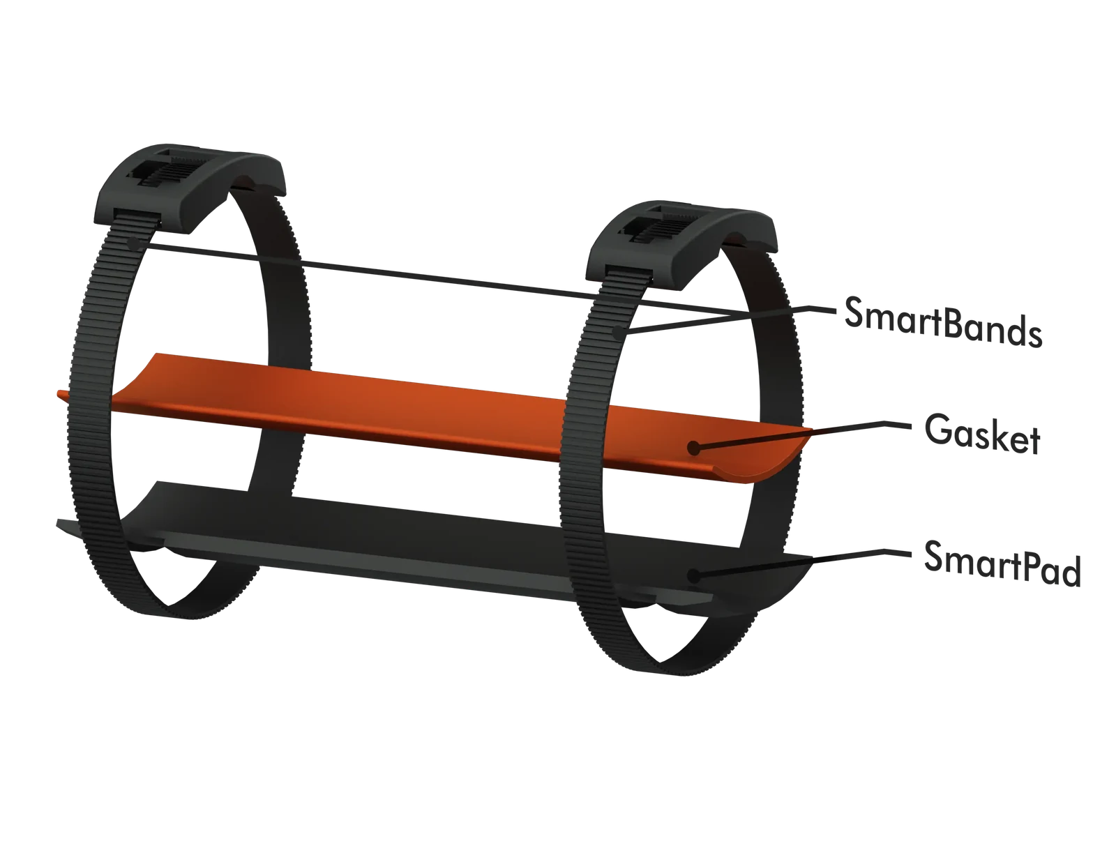
The standard system comprises four elements:
- A contoured FRP SmartPad saddle formed to match the pipe outside diameter and distribute bearing over a broad arc.
- A factory-bonded closed-cell Hydroseal gasket on the pipe-facing surface, selected for service temperature and chemistry.
- 19-mm (3/4-in.) PA66 SmartBand Standard bands and locking buckles located in recessed circumferential grooves.
- A SmartTool used to install, tension, and cut the retention bands in a repeatable manner.
4.2 Technical summary
| Property | Current technical reference basis | Evidence |
|---|---|---|
| Primary function | CUPS mitigation and pipe-support interface protection; removable inspection access | RedLineIPS product specification; EI CUPS context [1, 23] |
| Product size range | 1/2 in. through 72 in. NPS | RedLineIPS product specification [23] |
| FRP construction | Continuous-strand glass reinforcement in vinyl-ester resin matrix; contoured saddle geometry | RedLineIPS manufacturing data; INEOS resin data [12, 23] |
| FRP product temperature basis | Approximately -60°F to 400°F (-51°C to 204°C) for suitable configurations; actual assembly governed by lowest-rated component | RedLineIPS product specification [23] |
| Standard Hydroseal | Closed-cell silicone sponge; RedLineIPS data sheet identifies AMS 3195 basis; -103°F to 401°F (-75°C to 205°C) | RedLineIPS technical data sheet; SAE AMS3195 [10, 11] |
| Hydroseal installation basis | Approximately 30% gasket compression target for standard installation, subject to gasket/service configuration | RedLineIPS installation basis [23] |
| Water-sealing terminology | NEMA 4-level water-exclusion terminology for compressed interface; not SmartPad enclosure certification | RedLineIPS documentation; NEMA [15, 23] |
| Standard retention band | 19-mm (3/4-in.) HCL SmartBand Standard, PA66 | HCL [8] |
| HCL max system strength | 440 kgf / 969 lbf, measured on 600-mm test diameter | HCL [8] |
| HCL min system retention | 1,200 N / 122 kgf / 270 lbf with listed Standard 19-mm tools | HCL [8] |
| HCL Standard band temperature | 125°C / 257°F; life expectancy depends on working temperature | HCL [8] |
| RedLineIPS band-force model | Approx. 500 lbf per installed band assembly; approx. 1,000 lbf combined for two-band analytical basis | RedLineIPS engineering basis [23] |
| Attachment to pipe | Mechanical retention; no weld or epoxy bond to pipe | RedLineIPS product design [23] |
| Primary product-specific proof reports | HML 484-19: 113,300 lbf; HML 489-19: 26,400 lbf compression and 1,057 lbf shear | Houston Metallurgical Laboratory [13, 14] |
4.3 FRP SmartPad saddle
The saddle is a laminated glass-fiber/vinyl-ester composite formed to the pipe curvature. A broad saddle changes the mechanical contact from a narrow line or edge to a distributed bearing region. In first-order terms, average bearing pressure scales with applied reaction divided by effective bearing area; actual contact pressure is nonuniform and depends on saddle stiffness, pipe curvature, gasket compliance, support width, and load eccentricity. The purpose of the contoured geometry is therefore to reduce local pressure peaks and protect the coating, not to claim a uniform pressure field.
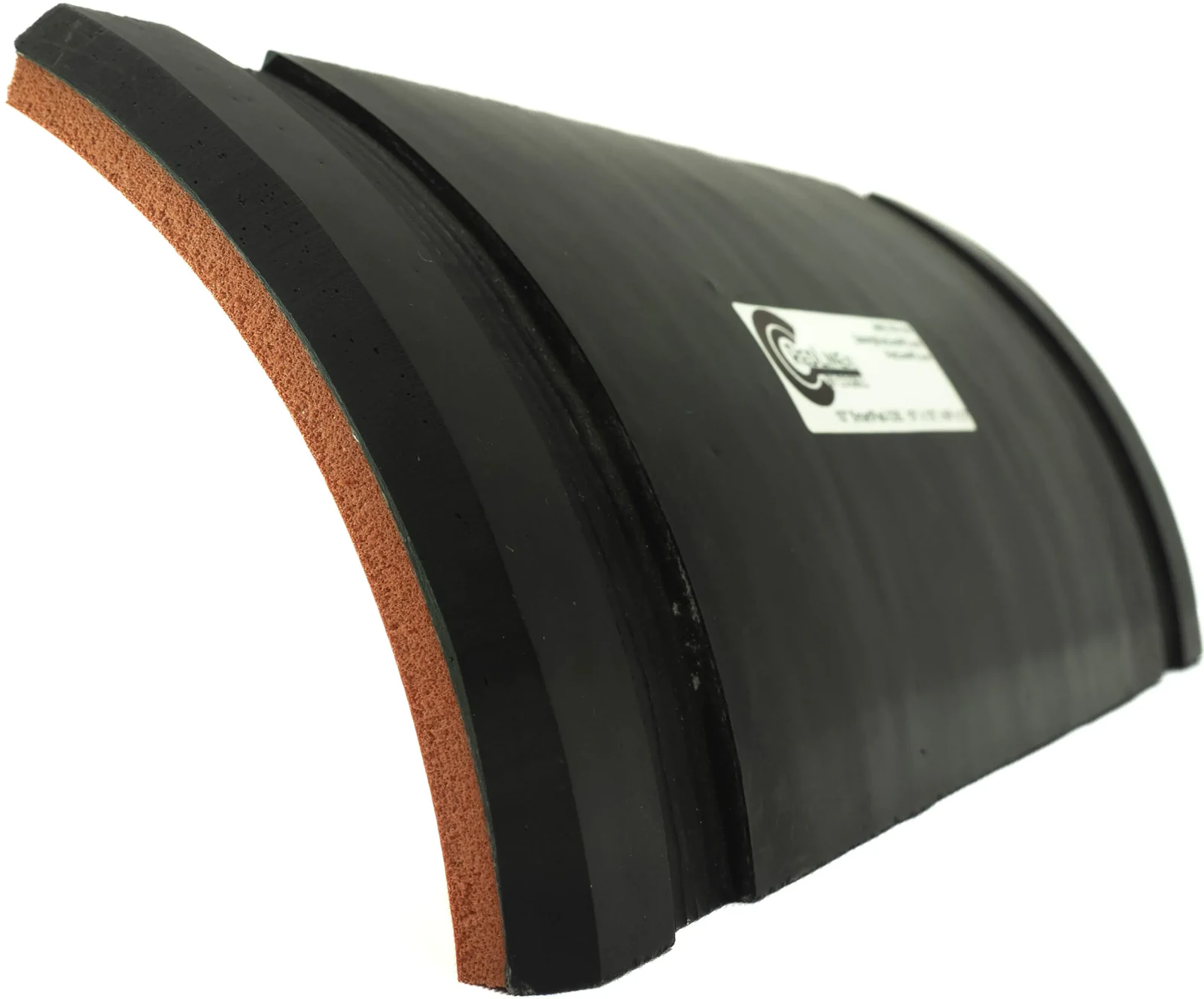
Recessed circumferential grooves locate the SmartBands and keep them from rubbing directly against the support. Sloped or radiused edges reduce sharp transitions and help alignment. The exterior FRP surface becomes the intended sacrificial sliding surface where normal thermal movement occurs over supporting steel.
The FRP is electrically nonmetallic at the contact interface. This interrupts direct metallic continuity through the support contact and can prevent the support from participating in a galvanic couple through that local path. It does not replace facility grounding, bonding, static-control, cathodic-protection continuity, or electrical-safety requirements.
4.4 Hydroseal closed-cell gasket
The Hydroseal gasket is factory-bonded to the pipe-facing side of the saddle. The current RedLineIPS technical data sheet identifies a medium closed-cell silicone sponge to an AMS 3195 basis and gives a service-temperature range of approximately -103°F to 401°F (-75°C to 205°C). SAE defines AMS3195 as closed-cell sponge supplied as sheet, strip, extrusion, or molded shapes; the current stabilized revision is AMS3195H. [10, 11]

The closed-cell structure is important because it does not intentionally provide the interconnected pore network characteristic of open-cell foam. When adequately compressed, the gasket conforms to coating texture and minor surface irregularities, reducing open crevice volume and limiting pathways for liquid entry. RedLineIPS installation guidance uses approximately 30% compression as the normal target for the standard gasket configuration. [23]
RedLineIPS documentation describes the compressed Hydroseal interface as providing NEMA 4-level watertight sealing performance. NEMA Type 4 is formally an electrical-enclosure classification that includes resistance to rain, splashing, and hose-directed water. NEMA also states that it develops standards rather than certifying products. Accordingly, this reference retains the NEMA 4 water-exclusion basis for the gasket interface but does not describe SmartPad as a NEMA-certified electrical enclosure. No IEC IPX6 qualification is claimed in this revision. [15, 23]
Closed-cell construction does not make damage irrelevant. A localized edge nick does not automatically convert the entire gasket into an open-cell wick, but damage that compromises gasket continuity, compression, adhesion, or conformal contact should be evaluated and the gasket/pad replaced when serviceability is uncertain.
4.5 SmartBand Standard retention system
The normal SmartPad retention system addressed in this reference is the SmartBand Standard in 19-mm (3/4-in.) PA66. RedLineIPS describes SmartBand Standard as a nonmetallic band-and-buckle system and publishes a maximum system strength of 440 kgf (969 lbf) for 19-mm PA66, measured on a 600-mm test diameter. RedLineIPS general product table lists a 75-mm minimum application diameter, an 800-mm (32-in.) maximum application diameter, and a 125°C (257°F) maximum temperature resistance for the PA66 Standard system. [8]

RedLineIPS also indicates a minimum system retention of 1,200 N (270 lbf) for the 19-mm Standard system with its listed SM-FT-1000-19 and SM-FT-2000-19 tools. It distinguishes maximum system force during tightening from minimum retained force after tool release and illustrates ideal band-leg tension as one-half of global system force. [8, 9]
SmartBands retain the SmartPad, maintain gasket engagement, and keep the saddle associated with the pipe during lifting, vibration, and movement. They are not intended to carry pipe deadweight in place of the structural support. This retention role is consistent with the band system being treated as a clamping/retention element rather than a lifting device or structural hanger.
4.6 SmartTool
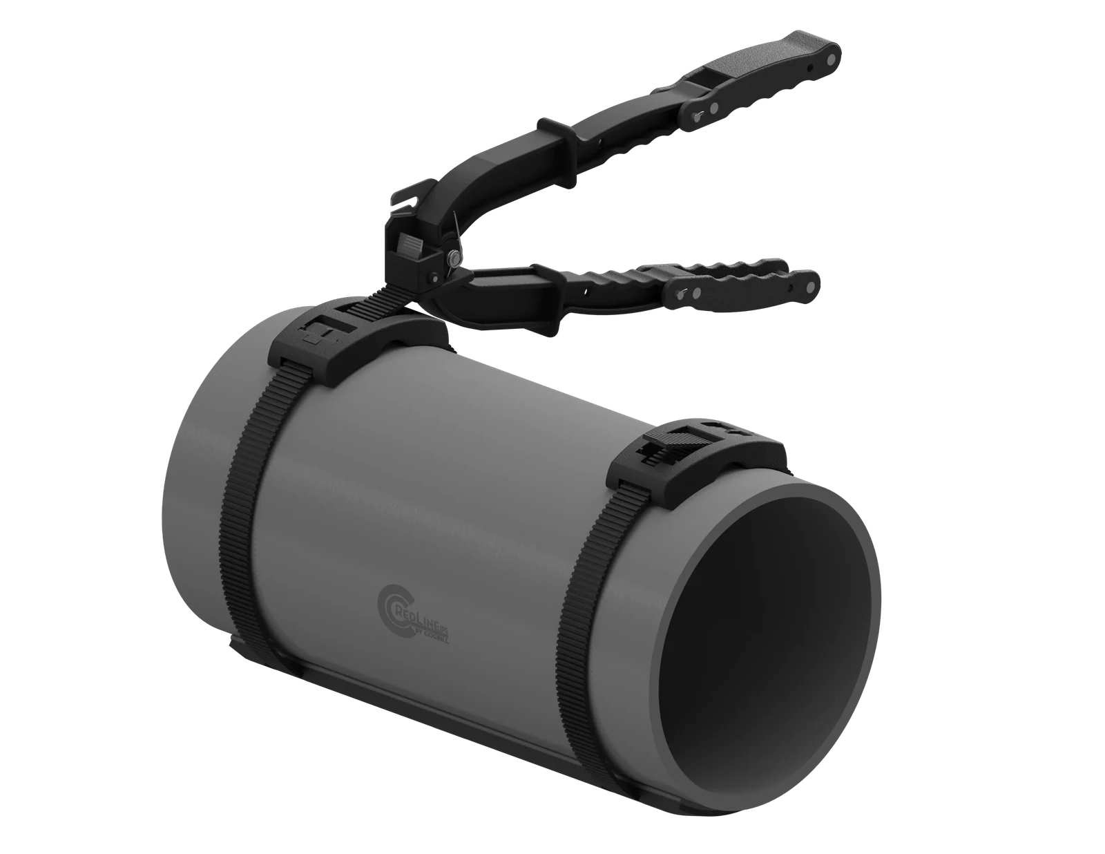
The SmartTool provides repeatable installation of the band system. RedLineIPS uses manual, mechanical, and pneumatic tooling configurations for different access and production requirements. HCL’s literature emphasizes that tool behavior, maximum tightening force, and retained force are distinct quantities. The field procedure should therefore use the specified SmartTool/RedLineIPS installation method rather than attempting to infer installation force from the published 969-lbf system-strength value. [8, 9, 23]
5. Interface Mechanics: Load Path, Friction, Thermal Movement, and Vibration
5.1 Vertical load path and bearing
For a normal resting support, the vertical load path is:
Pipe → compressed Hydroseal → FRP saddle → structural support
Pipe deadweight and operating reactions provide the primary normal bearing load. The bands add retention and gasket seating but do not replace the beam, shoe, or engineered support underneath the pipe.
A simplified average bearing-pressure expression is:
p_avg = W / A_eff
where W is the normal support reaction and A_eff is the effective bearing area. This is a screening relationship, not a contact-stress solution.
Real contact pressure depends on pipe and saddle curvature, gasket stiffness, support width, local flatness, laminate stiffness, edge effects, and eccentricity. Where local stress is a design concern, project-specific analysis or testing is appropriate; the 2019 proof tests should not be substituted for a complete support calculation.
5.2 Band force and gasket seating
RedLineIPS uses approximately 500 lbf per installed band assembly as a friction/retention modeling basis, or approximately 1,000 lbf combined for the usual two-band model. In HCL terminology this is best treated as a global system-force basis for each band assembly. HCL illustrates individual strap-leg tension as T = F/2; therefore “500 lbf per band” should not be reinterpreted as 500 lbf in each leg. [9, 23]
This analytical basis is separate from HCL’s published 969-lbf maximum system strength and 270-lbf minimum retained force for the Standard 19-mm system. None of those three numbers is a vertical pipe-support capacity. They answer different questions: proof/break behavior, retained clamping after tool release, and RedLineIPS interface modeling.
5.3 Preferred slip plane and friction model
A central SmartPad design principle is that the pipe, Hydroseal gasket, and SmartPad are intended to move together during normal thermal growth, while relative sliding occurs primarily between the exterior FRP saddle and supporting steel. The pipe coating therefore does not need to become the routine sliding surface. The first-order friction relationship is:
F_f = μN
F_f = friction force, μ = coefficient of friction, N = normal reaction
RedLineIPS has historically used representative engineering values of approximately μ ≈ 0.6 at the pipe-to-Hydroseal interface and μ ≈ 0.1 at the FRP-to-steel interface to explain the intended mechanism. Those values are illustrative, not certified coefficients for every coating, temperature, contamination level, wear state, or support finish. Where friction materially affects nozzle loads, anchor loads, thermal stress, guide reactions, equipment loads, or support-structure design, the piping/stress engineer should establish project-specific values.
The desired condition can be expressed conceptually as:
Force required to slide SmartPad on support < Force required to make pipe slip inside SmartPad
Engineering objective; not a universal numerical guarantee
A broad gasket footprint helps distribute pressure, accommodates surface texture, and stabilizes engagement. Under classical Coulomb friction, however, friction does not increase merely because apparent contact area increases. The dominant first-order variables remain the coefficient of friction and the normal/contact force.
5.4 Thermal movement
Thermal expansion is unavoidable in industrial piping. For a straight segment, axial growth can be estimated as:
ΔL = αLΔT
ΔL = change in length; α = coefficient of thermal expansion; L = original length; ΔT = temperature change
As an illustration, using α ≈ 6.5 × 10⁻⁶ in./in.-°F for carbon steel, a 100’ straight length subjected to a 100°F temperature increase expands approximately 0.78” before restraint effects are considered. SmartPad does not stop that movement. The expected travel must be accommodated by the overall piping support arrangement and by sufficient saddle/support overlap throughout the movement range.
SmartPad is therefore not a friction anchor, line stop, guide, hold-down, or seismic restraint. If axial movement must be limited, a separately engineered restraint must provide that function. If movement must be guided, the guide must be designed independently of the SmartPad interface.
5.5 Vibration and structure-borne noise
At a rigid pipe/support contact, dynamic excitation from pumps, compressors, turbulent flow, pulsation, hydraulic events, or structural flexibility can transmit through a hard metallic path into beams and deck members. The Hydroseal gasket introduces a compliant viscoelastic layer, while the broad saddle spreads local contact. These features can reduce local micro-slip, coating wear, and structure-borne transmission at the contact interface.
This effect must not be confused with system-level vibration control. SmartPad does not correct resonance, acoustic-induced vibration, flow-induced vibration, pulsation, poor alignment, inadequate bracing, or an incorrectly designed support system. If vibration threatens fatigue life, the owner should identify and correct the excitation and structural response using the appropriate vibration/fatigue engineering methods.
6. Material Selection and Environmental Limits
6.1 Vinyl-ester FRP and reinforcement
SmartPad uses a laminated glass-fiber/vinyl-ester composite rather than treating a resin data sheet as the finished product. Finished laminate behavior depends on fiber architecture, glass fraction, cure, laminate thickness, void content, orientation, temperature, and test geometry. This reference therefore does not assign a universal finished-SmartPad compressive or flexural design allowable based solely on resin-supplier properties.
DERAKANE 510 resin is used, and its data sheets indicate the use of novolac epoxy vinyl-ester. For one manufacturer-described laminate construction (two plies of 450 g/m² chopped-strand mat plus woven roving, approximately 40% glass content, with the stated post-cure), the data sheet reports approximately 21,000 psi tensile strength and 25,000 psi flexural strength. These are representative supplier laminate values for the stated construction—not guaranteed SmartPad properties and not allowable pipe-support reactions. [12]

6.2 Fire-retardant resin terminology
DERAKANE 510-family products are brominated epoxy vinyl-ester resins developed for corrosion resistance with fire-retardant behavior. The 510N data sheet describes a moderate degree of fire retardance and discusses ASTM E84 flame-spread performance for specified laminate formulations. Fire behavior depends on laminate construction, additives, thickness, cure, and the actual fire scenario. SmartPad should therefore be described as using a fire-retardant vinyl-ester formulation when the specified production laminate uses that resin system; it should not be described as fireproof or assigned a universal fire-survival time from resin data alone. [12]
6.3 Hydroseal silicone properties and temperature
The current RedLineIPS Cellular Silicone Elastomer technical data sheet identifies AMS 3195 closed-cell gasket with a temperature range of approximately -103°F to 401°F (-75°C to 205°C). The same sheet reports strong resistance to ozone, oxidation, ultraviolet exposure, corona discharge, cosmic radiation, ionizing radiation, and weathering, and it lists a low typical compression set under its stated test. [11]
The gasket selected for a project must remain compatible with operating temperature, pipe coating, external chemicals, washdown fluids, and expected compression. Alternative gasket materials may be appropriate for specific service; if the gasket is changed, the temperature, chemistry, compression, and water-exclusion basis must be re-established for that configuration.
6.4 Standard PA66 SmartBand temperature, conditioning, and stress relaxation
Published SmartBand data sheets indicate 125°C (257°F) as the maximum temperature resistance, and state that life expectancy depends on working temperature. [8] The polymer band is therefore often the lowest-temperature component in the standard SmartPad assembly even though the FRP saddle and silicone gasket may have higher temperature capability.
Technical literature also demonstrates that polymer conditioning, diameter, and time affect band behavior. Its tensile-test discussion notes that published system-strength data are for new, dry-as-molded specimens and may vary as polymers condition. Separately published data sheets include stress-relaxation data for selected SmartBand Hybrid/Compact configurations. Those data demonstrate the importance of polymer relaxation but should not be numerically transferred to the Standard buckle system unless HCL provides an applicable data set. [9]
6.5 Assembly temperature envelope
The installed assembly must be evaluated by the lowest-rated component at its actual service location. For the normal 19-mm PA66 Standard band configuration, the band temperature basis is approximately 257°F. RedLineIPS product literature identifies the FRP saddle basis as approximately -60°F to 400°F. Higher-temperature SmartPad configurations require a different retention strategy, such as stainless-steel bands, available upon request, and a gasket compatible with the actual service temperature; the FRP limit and project-specific material compatibility then govern. [8, 23]
6.6 Chemical and UV exposure
Vinyl-ester resins are widely used in corrosion-resistant FRP because chemical compatibility can be tailored through resin selection. INEOS publishes chemical-resistance guidance by chemical, concentration, and temperature for DERAKANE families. Such tables should be used as material-selection guidance, not as a blanket statement that every SmartPad configuration is resistant to every chemical. [12]
For aggressive splash, washdown, or process environments, the project should identify the external chemical, concentration, temperature, exposure duration, and cleaning regime. Gasket chemistry and any optional surface liner should then be selected accordingly. UV stabilization supports outdoor service, but UV resistance does not guarantee service life.
7. Primary Test Evidence and Engineering Interpretation
7.1 Houston Metallurgical Laboratory Test 484-19
Houston Metallurgical Laboratory, Inc. Test 484-19 is dated April 15, 2019, with a test date of March 27, 2019. The report identifies the specimen as “Large Diameter Wear Pad Compression Test” and describes one 16-in. OD × 3/8-in. wall × 14-in.-long gusseted pipe. The report records a compression load of 113,300 lbf and marks the report “For Information Only.” [13]
The report is primary third-party evidence that the tested wear-pad specimen was loaded to the stated force under the shown fixture. It does not establish a universal SmartPad allowable load, working load limit, safety factor, creep capacity, or fatigue rating.
7.2 Houston Metallurgical Laboratory Test 489-19
Houston Metallurgical Laboratory Test 489-19 is also dated April 15, 2019, with a test date of March 27, 2019. The specimen identification in the original report is “REDLINE PROTOTYPE,” not “SmartPad.” The compression report describes one 4-1/2-in. OD × 1/4-in. wall × 14-in.-long pipe and records 26,400 lbf on specimen 3. The shear report, titled “Report of Shear Test (Without Back Pads),” records 1,057 lbf on specimen 2. Both are marked “For Information Only.” [14]
7.3 Proof-test summary
| Report | Laboratory identification | Test | Recorded load | What the result establishes |
|---|---|---|---|---|
| HML 484-19 | Large Diameter FRP Pad Compression Test | Compression | 113,300 lbf | Load reached by the reported specimen/fixture; informational proof evidence only. |
| HML 489-19 | RedLine Prototype | Compression | 26,400 lbf | Load reached by the prototype assembly under the reported setup. |
| HML 489-19 | RedLine Prototype | Shear, without back pads | 1,057 lbf | Lateral/shear load reached by the prototype under the reported setup; not a guide/anchor rating. |
7.4 What the proof tests do not establish
The 2019 tests are short-duration monotonic tests on specific geometries. They do not define long-term creep, cyclic fatigue, temperature knockdown, chemical aging, UV aging, impact, support-edge effects, multi-axis interaction, installation variability, or a code-based allowable. A project engineer should not divide the reported loads by an arbitrary safety factor and call the result a SmartPad capacity without establishing a complete qualification basis.
ASTM D695 and ASTM D790 are useful standardized test methods for rigid-plastic compression and flexure, but a material test result still depends on specimen construction and test conditions. Appropriate engineering practice is to keep material coupon data, product proof tests, and supporting design calculations as separate evidence categories. [17, 18]
8. Installation and Retrofit Engineering
8.1 Pre-installation engineering checks
The direct SmartPad attachment process is simple; the engineering context around a support may not be. Before installation, confirm the support function and line condition. A resting support can often accept an interface pad without changing the piping restraint scheme, but a guide, anchor, line stop, hold-down, spring support, or support with significant lateral restraint requires engineering review before geometry or clearances are changed.
For retrofit work, the pipe surface should be exposed under an owner-approved lifting/unloading procedure, inspected, cleaned of loose corrosion products, and repaired/coated as required by the owner’s integrity program. SmartPad should not be installed as a way to conceal unevaluated corrosion.
8.2 Standard installation sequence
1. Verify pipe outside diameter, SmartPad fit, coverage angle, length, gasket type, band material, operating temperature, and support width/travel.
2. Provide safe access and, when necessary, temporarily unload or lift the pipe using an owner-approved method. Do not exceed piping/support allowable loads during lifting.
3. Inspect the exposed pipe and coating. Address corrosion, coating defects, debris, sharp protrusions, or contamination under the owner’s procedure before covering the area again.
4. Position the SmartPad so the support bears on the intended FRP region and the recessed band grooves remain clear of the support steel throughout expected movement.
5. Install the specified 19-mm PA66 SmartBands and buckles in the grooves. Tension using the specified SmartTool/RedLineIPS procedure.
6. Verify approximately 30% gasket compression for the standard Hydroseal configuration, uniform seating, band alignment, buckle engagement, clearance, and adequate saddle/support overlap for thermal travel.
7. Lower/reload the pipe in a controlled manner and verify that the SmartPad remains correctly positioned and that the support function, guide gaps, line-stop clearances, drainage, and adjacent components are unchanged or intentionally modified.
8.3 No welding or epoxy attachment
SmartPad is mechanically retained and therefore does not require welding, drilling, or an epoxy cure to attach the interface to the pipe. This can reduce hot-work and cure-time burdens compared with welded or bonded wear pads. It does not eliminate normal work controls: pipe lifting, work at height, access, dropped-object prevention, line condition, temporary support, and live-line procedures remain governed by the owner.
The phrase “installable on live lines” should therefore be understood as “the SmartPad attachment itself does not require a heat source or adhesive cure.” Whether a particular operating line may be lifted, unloaded, accessed, or modified is an owner/engineering decision. Energy Institute CUPS guidance specifically treats online versus offline remediation and line lifting as integrity-management issues. [1]
8.4 Large-diameter installations
Large-diameter piping increases circumference, handling effort, support reaction, travel, and the consequences of eccentric fit. For sizes above the 32-in. diameter range published in the general Standard-band table, RedLineIPS application practice governs the band layout and fit. Projects should verify band count, band spacing, buckle/tool access, pipe curvature fit, gasket continuity, support width, expected travel, and any need for installation aids. [8, 23]
9. Inspection, Maintenance, and NDT Integration
9.1 Lift–look–re-band inspection philosophy
The key inspection advantage of a removable support interface is direct access. For a normal inspection, the bands can be cut, the pipe safely unloaded/lifted as required, and the SmartPad removed to expose the actual pipe coating and steel surface. If the FRP saddle and bonded Hydroseal gasket remain serviceable, and they should, the same pad may be reinstalled using new band stock. The inspection cycle therefore converts a hidden support contact into an accessible maintenance location, rather than requiring the owner to infer condition through a permanent wear pad, or use expensive inspection methods such as ultrasound, X-Ray, EMAT, etc.
Direct visual examination should assess coating condition, rust staining, pitting, deposits, moisture, gasket imprint/contact, edge condition, contamination, band grooves, saddle wear, cracking/delamination, and support-steel condition. If corrosion is present or remaining wall is uncertain, quantitative NDT is still required.
9.2 NDT does not become unnecessary
Removability reduces the access barrier but does not make visual inspection a substitute for thickness measurement. HOIS/BINDT reports that CUPS inspection may require a combination of rapid screening and more quantitative techniques, with performance dependent on pipe diameter and wall thickness. Sonomatic and other industry sources describe long-range guided wave, EMAT, CHIME, multiskip, and related methods for inaccessible support regions. [2, 21, 22]
| Technique / approach | Typical role at CUPS locations | Important limitation |
|---|---|---|
| Direct visual after lift/removal | Coating condition, rust, deposits, pits, wetness, support condition | Does not quantify remaining wall where metal loss is present. |
| Conventional UT / encoded thickness mapping | Quantitative remaining thickness where surface access is available | Requires access/preparation and a qualified grid/scan plan. |
| Multiskip PAUT / related short-range methods | Screening and/or sizing through inaccessible support region | Performance depends on geometry, wall thickness, access, procedure, and validation. |
| CHIME / TOFD-derived medium-range techniques | Interrogate hidden region from adjacent access | Technique-specific setup and interpretation; not universally applicable. |
| EMAT / QSR-type methods | Non-contact or short-range screening/quantification in supported geometries | Equipment and geometry/thickness windows are technique-specific. |
| Long-range guided wave | Rapid screening of longer piping lengths and support populations | Primarily screening; follow-up NDT normally required to quantify local wall loss. |
| Radiography / digital radiography | Selected geometries where direct access is difficult | Radiation controls, access, orientation, sensitivity, and interpretation constraints. |
9.3 When wall loss is found
The appropriate response depends on severity, morphology, service, and applicable code. API 570 provides requirements for in-service piping inspection, rating, repair, and alteration; API RP 574 provides inspection practices and guidance for evaluating piping components; API 579-1/ASME FFS-1 provides fitness-for-service assessment methods. ASME B31.3 remains the process-piping design code for many of the facilities in which SmartPad is used. [3–6]
A SmartPad can be reinstalled after the owner has established that the pipe is acceptable for service and the surface is suitable, but the SmartPad itself does not change the remaining-wall calculation, allowable pressure, flaw assessment, or repair requirement. If a permanent repair is required, it must be designed and executed under the applicable owner/code repair process.
9.4 Inspection interval and condition-based maintenance
No single inspection interval is appropriate for every SmartPad. The interval should follow the owner’s risk-based or condition-based program and consider line service, consequence of failure, external environment, coating system, corrosion history, support population, inspection findings, and whether prior CUPS has occurred. Removability makes more frequent direct checks practical, but it does not replace risk ranking.
Treat bands and gasket surfaces as inspectable components. Replace banding after removal. Inspect the buckle, saddle, and bonded gasket before reuse. Replace the SmartPad if FRP cracking, delamination, severe wear, chemical attack, loss of gasket bond, permanent gasket damage, or geometry change could compromise seating or retention.
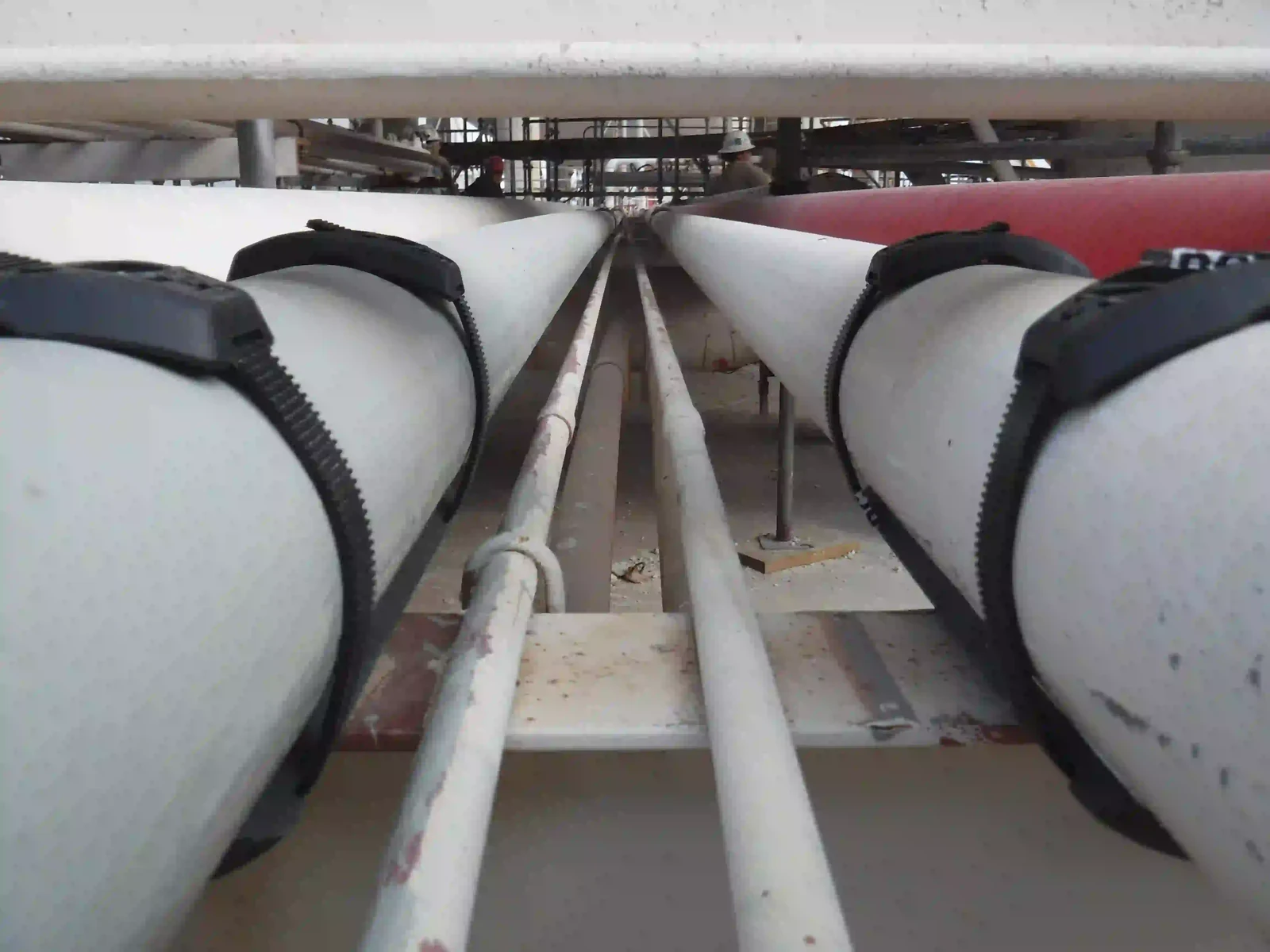
10. Field Evidence and Service Experience
10.1 Published Gulf of Mexico offshore case
A 2025 Offshore Magazine case study reports SmartPad installations on a Gulf of Mexico offshore platform beginning in 2019. The published chronology matters: detailed corrosion and acoustic observations were reported after about four years, while the first installations had reached about six years in service by the time of the 2025 publication. [19]
The case reported no active corrosion at treated interfaces during the cited checks and approximately 6–10 dB(A) lower spot sound readings at selected treated support locations than at nearby untreated locations under similar operating conditions. These observations are useful field evidence, but they are not a randomized corrosion trial or a controlled acoustic qualification. The sound readings should be described as field spot measurements, not a certified attenuation rating. [19]
10.2 Gulf Coast chemical-plant manufacturer field record
Separate RedLineIPS field documentation describes approximately 5,000 SmartPad support locations in Gulf Coast chemical-plant service, including multi-year inspection observations, nuisance-vibration observations, and field sound measurements. This experience is relevant because it represents a large support population in a hot, humid, salt-influenced industrial environment; however, it remains field evidence rather than independent controlled validation. [23]
10.3 What field evidence can and cannot prove
Field service can demonstrate installability, maintainability, inspection access, observed condition, and recurring operational experience. It does not by itself establish a universal corrosion rate of zero, a guaranteed fatigue-life extension, a statistically controlled noise reduction, or a fixed 20–30-year service life for every environment. Those conclusions would require controlled test protocols and defined exposure/load histories.
RedLineIPS has used a 20–30-year service-life expectation as a manufacturer design basis. This should be understood as an expectation dependent on temperature, chemical exposure, UV exposure, band relaxation, gasket condition, installation quality, and inspection history—not as 20–30 years of completed SmartPad field history and not as an unconditional warranty. HCL likewise states that polymer-system life expectancy depends on working temperature. [8, 23]
11. Engineering Comparison with Common CUPS Mitigation Approaches
No pipe-support interface is optimal for every service. The most useful comparison is not “which product is best,” but which failure modes and maintenance constraints each approach introduces.
| Approach | Engineering advantages | Primary considerations / limitations |
|---|---|---|
| Welded metallic wear pad or shoe | Robust structural attachment; familiar fabrication; can integrate restraint functions when engineered | Hot work and welding quality; coating repair; metallic contact path; permanent geometry can complicate underside inspection; not equivalent to removable CUPS interface. |
| Epoxy-bonded FRP wear pad | Nonmetallic interface; broad bearing; no welding to pipe; established FRP corrosion resistance | Surface preparation and cure; bond/seal quality depends on installation; difficult direct inspection beneath bonded pad; repairs on irregular pitted surfaces require care. |
| Thermoplastic rod / standoff | Drainage and ventilation; small moisture-retention footprint; nonmetallic isolation | Narrow contact can increase local bearing pressure; not a sealed interface; geometry and load distribution require review; inspection still requires access/lifting. |
| Elastomeric pad | Compliance and damping; coating protection | If not continuously sealed/drained, broad elastomer contact can retain moisture; temperature/chemical compatibility and compression set matter.. |
| SmartPad removable FRP + Hydroseal + bands | Broad contoured bearing; nonmetallic interface; compressed closed-cell gasket; no weld/epoxy attachment; removable for direct inspection; intended external slip plane | Requires correct gasket compression and band installation; band temperature/relaxation limits; not an anchor/guide/repair; large-diameter applications require product-level review. |
12. Project Specification and Design Guidance
12.1 Information required for a defensible application
A technical specification should define the service conditions rather than simply state a pipe size. At minimum, the purchaser/engineer should establish:
- Nominal pipe size and actual outside diameter, including coating/lining or dimensional features that affect fit.
- Support type and function: resting support, shoe, guide, hold-down, line stop, anchor, spring, or other restraint.
- Support width, bearing geometry, expected pipe reaction, lateral loads, and load eccentricity where known.
- Operating, design, startup, shutdown, and upset temperatures at the SmartPad, gasket, and band locations.
- Expected axial and lateral thermal travel and required minimum saddle/support overlap at both movement extremes.
- External environment: indoor/outdoor, coastal/marine, washdown, cooling-tower drift, salt, UV, chemical splash, immersion risk, and contaminants.
- Pipe coating system and any known compatibility restrictions with silicone, FRP, or cleaning chemicals.
- Inspection philosophy, access constraints, planned removal frequency, and whether direct UT mapping is expected.
- Electrical bonding/grounding/static-control requirements and any cathodic-protection continuity requirements.
- Applicable owner specifications, piping code, inspection code, and required documentation/acceptance criteria.
12.2 Suggested specification language
For a standard resting-support application, a technically defensible specification can describe SmartPad as a removable FRP saddle with factory-bonded closed-cell silicone gasket and 19-mm PA66 nonmetallic retention bands, sized to the actual pipe outside diameter, installed to the manufacturer’s gasket-compression and banding procedure, with adequate pad length for calculated thermal travel and with future removal for direct inspection. It should separately state that structural support reactions, restraint functions, piping stress, and fitness-for-service remain the owner/engineer’s responsibility.
12.3 Acceptance checks after installation
- SmartPad fully seated to pipe curvature with no visible rocking or gross mismatch.
- Hydroseal gasket visibly continuous at accessible edges and compressed approximately to the specified target for the selected gasket.
- Bands correctly routed in recessed grooves, buckles fully engaged, tails cut/finished, and no band bearing directly on support steel.
- Pad centered on intended support bearing region with sufficient overlap for calculated movement in both directions.
- Guide/hold-down/line-stop clearances verified where applicable; no unintended new restraint created.
- No damage to pipe coating, gasket, FRP, bands, or adjacent support components during installation.
- Installation record identifies location, date, pipe size, SmartPad configuration, gasket/band configuration, and inspector/installer.
13. Frequently Asked Engineering Questions
13.1 Does SmartPad carry the pipe load?
The structural support carries the pipe reaction. SmartPad is an interface in that load path. The FRP saddle and gasket transfer the reaction into the supporting structure, while the bands retain the SmartPad and maintain gasket engagement.
13.2 Is 113,300 lbf the allowable load of a SmartPad?
No. HML Test 484-19 records 113,300 lbf on a specific Large Diameter Wear Pad Compression Test specimen. The report is “For Information Only” and does not define a working load limit, fatigue rating, or universal allowable.
13.3 Do two SmartBands provide 1,000 lbf of pipe-support capacity?
No. Approximately 500 lbf per installed band assembly and approximately 1,000 lbf combined are RedLineIPS retention/friction-model values. They are not vertical support capacities and are distinct from SmartBand maximum strength and retained-force data.
13.4 Does the gasket have a NEMA 4 rating?
RedLineIPS retains NEMA 4-level water-exclusion terminology for the properly compressed Hydroseal interface. NEMA Type 4 is formally an enclosure classification, so this reference does not claim the SmartPad assembly is a NEMA-certified electrical enclosure.
13.5 Is SmartPad IPX6 certified?
No. No IEC IPX6 qualification is claimed in this revision.
13.6 Does SmartPad eliminate CUPS?
It is designed to mitigate major CUPS drivers at the treated interface: coating abrasion, moisture entry, direct metallic contact, and lack of inspection access. It also does not address unrelated internal corrosion or degradation outside the protected footprint.
13.7 Can SmartPad be installed over existing corrosion?
Only after the owner has exposed, inspected, evaluated, and remediated the pipe as required. SmartPad is not a repair for lost wall thickness. Its conformal gasket can accommodate normal surface irregularity after the pipe has been accepted for service.
13.8 Does SmartPad eliminate NDT?
No. It can make direct visual examination much easier, but UT or other NDT remains appropriate when remaining wall thickness or hidden degradation must be quantified.
13.9 Where should thermal sliding occur?
The intended slip plane is primarily between the exterior FRP saddle and the structural support, while the pipe, gasket, and SmartPad move together. Project-specific stress analysis governs where friction values matter.
13.10 Is SmartPad a guide, anchor, or line stop?
No, unless a separately engineered restraint arrangement provides and verifies that function. SmartPad should not be credited as a positive piping restraint by default.
13.11 Can the SmartPad be reused after inspection?
If the FRP saddle and bonded Hydroseal remain serviceable, they may normally be reused. The removed banding is replaced with new band stock and the assembly is reinstalled according to the specified procedure.
13.12 What controls maximum temperature?
The lowest-rated component in the installed configuration. The normal 19-mm PA66 Standard band has a published 125°C / 257°F temperature basis, which is below the RedLineIPS FRP product basis. Higher-temperature configurations require different retention/gasket selection, such as stainless steel banding.
13.13 Does the nonmetallic interface replace grounding or bonding?
No. Local dielectric isolation at the support contact does not replace project-required bonding, grounding, static control, or cathodic-protection continuity.
14. Limitations, Design Responsibility, and Use of This Reference
This document is a technical reference for the SmartPad pipe-support interface and the evidence supporting its use. It is not a piping code, structural design standard, pressure-boundary repair procedure, fitness-for-service assessment, inspection procedure qualification, or warranty. The owner and responsible engineer remain responsible for the piping system and support design.
SmartPad performance depends on correct product selection, fit, gasket compression, band installation, support geometry, temperature, chemistry, coating condition, travel, maintenance, and inspection. The system does not guarantee zero corrosion, zero vibration, zero noise, infinite band retention, or a fixed service life. Published laboratory loads and field observations must remain within the scope of the reported specimens and methods.
Where this article cites external standards, only high-level roles and publicly available information are summarized. The controlling edition and full requirements of any purchased code or standard must be applied by the project. If a project specification conflicts with this reference, the project engineer and RedLineIPS should resolve the application before installation.
15. Conclusion
CUPS is difficult because it combines electrochemical degradation with a mechanical contact that is hard to inspect. A durable solution must therefore address more than corrosion chemistry. It must protect the coating, manage moisture and contaminants, distribute bearing load, accommodate thermal movement, avoid creating unintended restraint, and preserve access to the pressure boundary.
The RedLineIPS SmartPad System addresses those interface requirements with a removable FRP saddle, closed-cell Hydroseal gasket, nonmetallic SmartBand retention, and repeatable tooling. The strongest evidence supporting the system is not any single marketing claim: it is the combined source chain of original HML proof reports, component data, silicone and resin technical data, industry CUPS guidance, published offshore service observations, and manufacturer field experience—each interpreted within its proper boundary.
For engineering use, the key discipline is source separation. The 113,300-lbf, 26,400-lbf, and 1,057-lbf results are proof-test observations; the 969-lbf HCL figure is a maximum band-system strength; the 270-lbf HCL value is a minimum retained-force figure under specified tooling; the approximately 500-lbf-per-band value is a RedLineIPS modeling basis; NEMA 4 terminology describes water-exclusion performance at the gasket interface rather than an enclosure certification; and the 20–30-year service-life figure remains a manufacturer expectation rather than completed field history. With those distinctions maintained, SmartPad can be specified and evaluated as a serious pipe-support interface technology rather than as a collection of unqualified performance claims.
Appendix A. Key Claim-to-Evidence Map
| Key claim | Evidence source | Status / qualification |
|---|---|---|
| CUPS is a significant localized integrity threat with inspection difficulty | Energy Institute; HOIS/BINDT [1, 2] | Independent industry guidance. |
| SmartPad product range 1/2–72 in. NPS | RedLineIPS product specification [23] | Manufacturer product range. |
| 19-mm PA66 SmartBand Standard; 969 lbf max system strength; 257°F max temp; 32-in. public max diameter | HCL Smart Products brochure [8] | Component-manufacturer published data. |
| 270 lbf minimum Standard-system retention with listed tools | HCL Smart Products brochure [8] | Component-manufacturer test basis; not installation preload. |
| 500 lbf per band / 1,000 lbf two-band analytical basis | RedLineIPS engineering model [23] | Manufacturer modeling basis; not HCL rating. |
| Hydroseal closed-cell silicone; AMS3195 basis; -103°F to 401°F | RedLineIPS technical data sheet; SAE [10, 11] | Manufacturer/specification basis. |
| Approx. 30% standard Hydroseal compression target | RedLineIPS installation basis [23] | Manufacturer installation practice. |
| NEMA 4-level water exclusion | RedLineIPS gasket/interface documentation; NEMA context [15, 23] | Retained as interface water-sealing terminology; not SmartPad enclosure certification. |
| 113,300 lbf compression | HML Test 484-19 [13] | Third-party “For Information Only” proof report; no universal allowable. |
| 26,400 lbf compression / 1,057 lbf shear | HML Test 489-19 [14] | RedLine HDC Prototype proof report; not relabeled as final SmartPad capacity. |
| 4-year corrosion/noise observations; 6-year in-service chronology | Offshore Magazine case [19] | Published field case; observational evidence. |
| Approx. 5,000 Gulf Coast support locations | RedLineIPS field records [23] | Manufacturer field experience; not an independent controlled study. |
| 20–30-year service-life expectation | RedLineIPS engineering expectation [23] | Not completed field history or blanket warranty. |
Appendix B. Inspection Record Minimum Data Set
For owners seeking traceable SmartPad inspection data, the following minimum fields are recommended so that condition can be compared across inspection cycles and support populations:
- Asset / line number, support location ID, unit/area, GPS or drawing reference when used by the site.
- Pipe NPS/OD, material, coating system, design/operating temperature, and service description.
- SmartPad size, length, coverage, gasket type, band material, installation date, and prior inspection date.
- As-found band/buckle condition and SmartPad position relative to the support.
- Gasket edge/adhesion/compression condition and evidence of moisture or contamination.
- Pipe coating condition, rust staining, pit morphology, deposit condition, and photographs after removal.
- UT/NDT method and results where metal loss is present or suspected, including minimum thickness and scan/grid reference.
- Support steel condition, contact wear, sharp edges, debris, drainage, and evidence of unintended movement/restraint.
- Disposition: reuse pad, replace gasket/pad, replace bands, repair coating, perform FFS/engineering review, repair pipe, or other action.
- Inspector, date, procedure/reference, instrument ID/calibration where NDT is used, and next inspection due date.
16. Technical References and Supporting Publications
[1] Energy Institute, Guidelines for the Integrity Management of Corrosion Under Pipe Supports (CUPS), 1st ed., October 2018, ISBN 9780852939857. https://www.energyinst.org/industry/publications/topics/asset-integrity/guidelines-for-the-integrity-management-of-corrosion-under-pipe-supports-cups
[2] S. F. Burch and H. R. Peramatzis, “Inspection of Corrosion Under Pipe Supports (CUPS),” ESR Technology / HOIS, BINDT NDT 2019. https://www.bindt.org/events-and-awards/NDT-2019/inspection-of-corrosion-under-pipe-supports-cups/
[3] American Petroleum Institute, API 570, Piping Inspection Code: In-service Inspection, Rating, Repair, and Alteration of Piping Systems, 5th ed., February 2024. https://www.api.org/products-and-services/standards/important-standards-announcements/std570
[4] American Petroleum Institute, API RP 574, Inspection Practices for Piping System Components, 5th ed., February 2024. https://www.api.org/products-and-services/standards/important-standards-announcements/rp574
[5] API 579-1/ASME FFS-1, Fitness-For-Service, 2021 edition. https://www.asme.org/getmedia/5726e673-eb65-456e-913d-3d0dce0359ff/asme-ffs-1_2021_toc.pdf
[6] ASME B31.3, Process Piping, 2024 edition. https://www.asme.org/codes-standards/find-codes-standards/b31-3-process-piping
[7] P. Krishnasamy, “Assessment and Rehabilitation of Corrosion Under Pipe Supports (CUPS): Development and Validation of a Structured Integrity Decision Model,” IEM Journal, Vol. 87, No. 3, September 2026, DOI 10.54552/9b7tkz23. https://doi.org/10.54552/9b7tkz23
[8] HCL Fasteners Ltd., Smart Products brochure, SmartBand Standard 19-mm PA66 performance, diameter, temperature, and retention data. https://hclfasteners.com/brochures/Smart_Products_Brochure_Final.pdf
[9] HCL Fasteners Ltd., Smart Products Technical Booklet, system force, fitting tools, tensile testing, conditioning, and stress-relaxation guidance. https://hclfasteners.com/brochures/HCL_Smart_Products_Technical_Compressed.pdf
[10] SAE International, AMS3195H, Silicone Rubber Sponge, Closed Cell, Medium, stabilized June 2019; historical project documentation may reference earlier revisions including AMS3195E. https://saemobilus.sae.org/standards/ams3195h-silicone-rubber-sponge-closed-cell-medium
[11] RedLineIPS / Cogbill Construction, Technical Datasheet: Cellular Silicone Elastomer, Sheeting Grade AMS 3195, project technical archive, reviewed 2026.
[12] INEOS Composites, DERAKANE 510N Epoxy Vinyl Ester Resin technical data and DERAKANE Resin Selection Guide for Chemical Resistance, project archive/current manufacturer literature. https://www.ineos.com/globalassets/ineos-group/businesses/ineos-composites/markets/corrosion/derakane-resin-selection-guide.pdf
[13] Houston Metallurgical Laboratory, Inc., Test No. 484-19, Large Diameter Wear Pad Compression Test, test date March 27, 2019; report date April 15, 2019; “For Information Only.”
[14] Houston Metallurgical Laboratory, Inc., Test No. 489-19, RedLine HDC Prototype compression and shear testing, test date March 27, 2019; report date April 15, 2019; “For Information Only.”
[15] National Electrical Manufacturers Association, NEMA 250 enclosure standard information and NEMA enclosure guidance/FAQ. https://www.nema.org/standards/view/enclosures-for-electrical-equipment-1000-volts-maximum
[16] ASTM International, ASTM D1056, Standard Specification for Flexible Cellular Materials—Sponge or Expanded Rubber. https://store.astm.org/standards/d1056
[17] ASTM International, ASTM D695, Standard Test Method for Compressive Properties of Rigid Plastics. https://store.astm.org/d0695-26.html
[18] ASTM International, ASTM D790, Standard Test Methods for Flexural Properties of Unreinforced and Reinforced Plastics and Electrical Insulating Materials. https://store.astm.org/standards/d790
[19] H. Almufti, “Case Study: System Cuts Corrosion Risk and Noise on a Gulf of Mexico Offshore Platform,” Offshore Magazine, October 1, 2025. https://www.offshore-mag.com/pipelines/article/55320487/case-study-system-cuts-corrosion-risk-and-noise-on-a-gulf-of-mexico-offshore-platform
[20] Institute of Corrosion, “Combatting Corrosion, Vibration, and Fatigue Under Pipe Supports: SmartPad System Advances for the Energy and Process Sectors,” Corrosion Management / ICorr technical article, 2025. https://www.icorr.org/combatting-corrosion-vibration-and-fatigue-under-pipe-supports-smartpad-system-advances-for-the-energy-and-process-sectors/
[21] Sonomatic Ltd., Inspection for Corrosion Under Pipe Supports (CUPS), technical presentation, 2018; included in project reference archive.
[22] Acuren, Corrosion Under Pipe Supports: Your Turnkey Access Solution, technical/service brochure; included in project reference archive.
[23] RedLineIPS / Cogbill Construction, SmartPad System product specifications, friction/thermal-movement engineering notes, installation guidance, and manufacturer field records, project technical archive, reviewed November 2026.
[24] DNV, “Preventing External Corrosion Failures,” technical article on external corrosion and coating/environment considerations. https://www.dnv.com/energy/services/laboratories-test-facilities/article/preventing-external-corrosion-failures/
Source-control note: External standards and manufacturer documents should be checked for the current controlling edition when used on a project. This article records the editions and public data verified during the November 2026 technical review.
About Hani Almufti
Engineer & Senior Manager, Cogbill Construction (RedLineIPS)
Hani is an industrial engineer with 15 years in pipe supports and 10 years in offshore energy corrosion. His work includes product strategy, materials selection and technical guidance for metallic and nonmetallic supports, with expertise in CUPS, corrosion mitigation, reliability and lifecycle performance.
Explore Technical Reference articles · Browse product resources